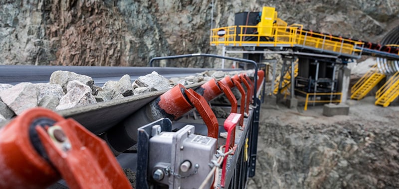
Dry Bulk Conveyors

Basic Design For Better Maintenance

Dry bulk material producers and handlers spend millions of dollars every year maintaining conveyor systems. Often, conveyor design does not provide the means for ease of maintenance, and as a result, maintenance may not be performed correctly, on time, or at all. This eventually leads to a greater risk of component failure and a resulting loss of production.

Designing a conveyor to be maintenance friendly means providing adequate provisions for necessary service from the onset. This means eliminating problems such as inadequate spacing, inaccessible positions, and other non-repairable configurations. The following sections will illustrate some of the design considerations that may deter or aid in conveyor maintenance.


Material Characteristics

When designing a conveyor, the type of material to be conveyed is the first item to be taken into consideration. The flowability of a material affects the size of the cross section of load that can be carried on a given belt width. Flowability is affected by
material characteristics such as:

  • Size and Shape
  • Roughness or Smoothness
  • Proportion of Fines and Lumps
  • Moisture Content
  • Weight per Cubic Foot
  • Abrasiveness
  • Temperature

Belt Width, Speed & Capacity

For a given speed and material density, the wider the conveyor belt the higher the capacity of the conveyor. A belt must be wide enough so that the combination of fines and lumps do not push the lumps too close to the edge of the belt. The chart below shows the belt width necessary for a specific lump size, various proportions of lumps and fines, and various surcharge angles.

Conveyor belt speeds depend upon the material characteristics, the capacity desired, and belt tensions. Heavy materials with sharp edges should be conveyed at moderate speeds. The sharp edges will cause wear to the belt, particularly if the loading velocity of the material in the direction of belt travel is lower than the conveyor belt speed.

Light, powdery materials must also be conveyed at lower speeds to reduce dust particles, especially at loading and discharge points on the conveyor. Fragile materials may degrade at loading and discharge points, as well as when moved over idlers. Therefore, these types of materials should also be conveyed at lower speeds.

It is important to know the tons per hour (TPH) of material an end user expects to move with a conveyor. If there is uniform feed to the conveyor, a cross section of the material loaded on the belt is used in calculating the capacity of a conveyor. The cross section of material must meet the following two conditions. 

  1. Material does not extend beyond to the belt edge
  2. Top of load does not exceed surcharge angle of loading
Conveyor Belt Speed Recommendations
Material_Belt_Width_2

Conveyor Belt Material

The three elements of a conveyor belt are the carcass, top cover, and bottom cover. The carcass of the belt must have the tensile strength to withstand the load on the belt, and it must also have the strength to withstand the impact of materials in loading areas.

Most carcasses consist of multi-ply woven fabrics. Heavier duty belt carcasses may contain steel cables for reinforcement. The yarns of a belt carcass that run parallel to the conveyor are called warp yarns. These bear the tension of the belt. The cross yarns of the belt carcass are called weft yarns and aid in impact resistance.

  • Multi-Ply: Usually made up of three plies semented together by a compound. Strength and load support depend on layer numbers.
  • Reduced-Ply: Usually consists of fewer layers, but the layers are made of synthetic fabrics of higher unit strength.
  • Steel Cable: Consists of a layer of steel cables embedded in rubber. It's best used where tensions required go beyond ply carcasses.
  • Solid Woven: A single ply of solid woven fabric usually covered with a top and bottom cover made of PVC material for abrasion resistance.

The required length of a belt can be computed by multiplying the conveyor length by two and adding the length needed to wrap around head and tail pulleys. A gravity takeup on a channel frame conveyor will require an additional 6-feet of belt, while a gravity take-up on a truss frame conveyor will require an additional 10-feet.

Idler Selection

All belt conveyor idlers have the same purpose. They provide shape and support for the belting and minimize the power needed to transport material. Idler spacing affects both the shape and support of the conveyor belt. Idlers placed too far apart will not properly support the belt or enable it to maintain the desired profile.

Idlers that are placed too close together will provide the necessary support and profile, but may add unnecessary expense to the conveyor. The main influences in idler selection are belt and material weight, idler load rating, belt sag, idler life, belt rating, and belt tension.

Suggested idler spacing recommendations are listed below (under normal operating conditions when the amount of belt sag is not specifically limited). This table also shows the recommended spacing for return idlers.

Idler Spacing Recommendations
troughing idler spacing

Pulley Selection

The standardization of pulleys lends itself to the ease of choosing the correct pulley for a given application. The most commonly used pulley is the standard steel pulley. Plain steel drum pulleys are best used in dry clean environments where traction is not critical, and when no foreign material is present on the return belt.

Conveyor pulleys may also be covered with rubber, fabric, or other material. This is referred to as lagging. Lagging on a drive pulley provides an increase in the friction between the belt and the pulley. Lagging is also used to reduce abrasive wear to the face of the pulley and to create a self-cleaning action on the surface of the pulley.

Wing pulleys are typically used in tail pulley applications to reduce the buildup of material between the belt and pulley. Trapped materials fall through the paddlelike formations of the pulley. 

The conventional wing pulley is particularly susceptible to material buildup, wing bending, as well as noise and vibration during operation. Belts and tail pulleys are subject to damage and failures when fugitive material becomes entrapped between the belt and the tail pulley. If the material is not removed, several issues can occur:
  • Material carried between belt and pulley cause excess belt wear.
  • Large entrapped material can puncture, gouge or rip the belt.
  • Entrapped material can bend the pulleys wings.

In 2007, Superior engineered a new v-shaped wing pulley to prevent material buildup and belt damage while greatly minimizing noise and vibration during operation. When compared to the conventional wing pulley, the v-shaped design delivers numerous time-and -money saving advantages over that of traditional choices.

Shafting is commonly considered to be a part of the pulley assembly since the strength and rigidity of the assembly depends on both of these components. When choosing shaft diameter, it is important to consider both the shaft diameter required for strength and shaft diameter required for deflection. Depending on the pulley assembly, either strength or deflection may be the deciding factor of shaft diameter.

Mainland Construction Materials 2019-03_130 copy

Scraper Selection

Carryback is the fugitive material that sticks to the belt after it passes over the head pulley and subsequently creates fugitive material piles along the underside of the conveyor. Fugitive material is a costly problem, considering that many maintenance hours are spent cleaning these piles.

In order to correct carryback, a belt cleaner is used. This is usually a form of a wiper, blade or scraper device mounted near the discharge (head) pulley.

A common type of belt cleaner is the precleaner. This is often referred to as the primary cleaner and functions by scraping off most of the carryback leaving only a thin layer of fines on the belt. The pre-cleaner is mounted on the face of the head pulley just below the discharge trajectory. This allows the material scraped from the belt to fall with the discharge materials.

Secondary cleaners are designed to remove the thin layer of fines left by the precleaner. It’s best to place the secondary cleaner in contact with the belt while it is still against the head pulley. This enables the cleaner to scrape against a firm surface.

If you require both primary and secondary cleaning, but your conveyor is not designed to accommodate the secondary cleaner, look for technology that combines primary and secondary blades with one shared mounting pole.

There are several types of non-traditional belt cleaners to eliminate carryback.

  • Effective on dry materials, brushes can be driven by the pulley.
  • Pneumatic cleaners send air across the face of the pulley.
  • Mist of water sprays on the belt to make scraping process easier.
  • High-pressure water to completely remove carryback.
Return belt cleaner systems, also known as v-plows, are used to prevent large objects and tramp iron on top of the return belt from damaging conveyor components. A low pressure mechanical scraping is used to remove the material from the belt.

Take-Up Selection

Conveyors need take-ups to ensure proper belt tension, which prevents belt slippage and material spillage. They also compensate for belt shrinkage or stretch.

The required take-up movement length is determined by the type of mechanism being used to start and stop the conveyor, the frequency of starts and stops with a loaded belt, stretch characteristics of the belt, and running tensions.

There are two types of take-up systems, manual and automatic. The manual systems are preferred when an automatic take-up is impractical like operation of short, light conveyors.

Transfer Points

A transfer point is any point on the conveyor where material is loaded onto or unloaded from the conveyor belt. The ideal transfer point would be designed to load the belt in the center and at a uniform rate. They should also reduce the impact of the material falling on the belt and maintain a minimum angle of inclination of the belt at the loading point.

The design of discharge chutes and other loading equipment should take these topics into consideration. Other factors such as capacity, size, characteristics of material, speed, and inclination of the belt should also be considered.

Transfer point structures can rapidly deteriorate due to impact from heavy objects or material with sharp edges. Load zone impacts also cause wear and damage to the conveyor belt, weakening its carcass.

To aid in the prevention of this damage, transfer points should be designed to lessen the height of the material drop. There are also devices made to reduce impact at transfer points. Impact troughing idlers have rubber cushioned rollers to absorb impact. Beds or cradles can also be positioned under the belt to absorb impact.

National Gypsum_Winkelman AZ_6-18-2024_123

Related Content

Related Content 010 - Dont Overlook This Critical Component

010: Conveyor Idlers: Don't Overlook This Critical Component

While reliability of each conveyor component is key, it’s the often overlooked idler that should always receive proper consideration.

Related Content 013 - Conveyor Snub Pulleys- A Simple Solution to Belt Slippage

013: 
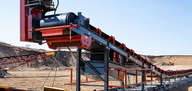
Conveyor Snub Pulleys: A Simple Solution to Belt Slippage

Mounted close to the drive pulley, the snubs primary job is to increase wrap angle around the drive pulley, thereby increasing traction.
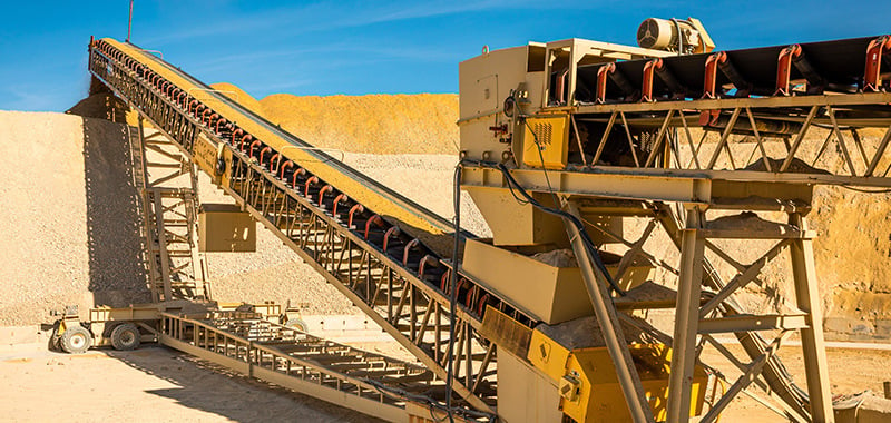
Related Content 015 - Useful Transfer Point Tips

015: Dry Bulk Conveyors: Useful Transfer Point Tips

Preventing spillage at transfer points is imperative, since cost reductions from elimination at one transfer are significant.

Talk to an Expert

Need more information? We'll get you in contact with a product expert in your area.